ICP® is a term that uniquely identifies PCB's piezoelectric sensors with built-in microelectronic amplifiers. (ICP® is a registered trademark of PCB Group, Inc.) Powered by constant current signal conditioners, the result is an easy-to-operate, low-impedance, two-wire system as shown in Figure 5.
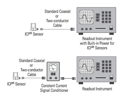
Figure 5: Typical ICP
® Sensor Systems
In addition to ease-of-use and simplicity of operation, ICP® sensors offer many advantages over traditional charge output sensors, including:
1.) Fixed voltage sensitivity independent of cable length or capacitance.
2.) Low output impedance (<100 Ohms) allows signals to transmitted over long cables through harsh environments with virtually no loss in signal quality.
3.) Two wire system accommodates standard low cost coaxial or other two conductor cable.
4.) High quality, voltage output compatible with standard readout, recording or acquisition instruments.
5.) Intrinsic sensor self-test feature by monitoring sensor output bias voltage.
6.) Low per channel cost as sensors require only low cost constant current signals conditioners.
7.) Reduced system maintenance.
8.) Direction operation into readout and data acquisition instruments which incorporate power for use with PCB's ICP® sensors.
Figure 6 schematically shows the electrical fundamentals of typical quartz and ceramic ICP® sensors. These sensors are comprised of a basic piezoelectric transduction mechanism (which has an output proportional to force, pressure acceleration, or strain, depending on the sensor type) coupled to a highly reliable integrated circuit.
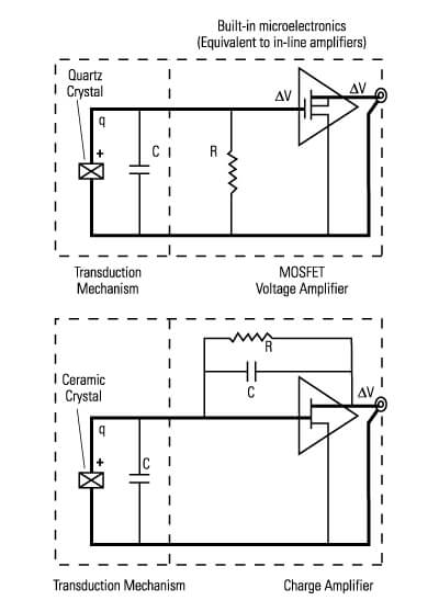
Figure 6: Basic Quartz and Ceramic ICP
® Sensors
Two types of integrated circuits are generally used in ICP® sensors: voltage amplifiers and charge amplifiers. Low capacitance quartz sensing elements exhibit a very high voltage output (according to V = q/C) and are typically used with MOSFET voltage amplifiers. Ceramic sensing elements which exhibit a very high charge output are normally coupled to charge amplifiers.
The theory behind ICP® quartz sensing technology will first be explained. The process begins when a measurand, acting upon the piezoelectric sensing element, produces a quantity of charge referred to as ∆q. This charge collects in the crystal capacitance, C, and forms a voltage according to the law of electrostatics: ∆V = ∆q/C. Because quartz exhibits a very low capacitance, the result is a high-voltage output, suitable for use with voltage amplifiers. The gain of the amplifier then determines the sensor sensitivity.
This ∆V instantaneously appears at the output of the voltage amplifier, added to an approximate +10 VDC bias level. This bias level is constant and results from the electrical properties of the amplifier itself. (Normally, the bias level is removed by an external signal conditioner before analyzing any data. This concept will be fully explained later.) Also, the impedance level at the output of the sensor is less than 100 ohms. This makes it easy to drive long cables through harsh environments with virtually no loss in signal quality.
ICP® sensors which utilize ceramic sensing elements generally operate in a different manner. Instead of using the voltage generated across the crystal, ceramic ICP® sensors operate with charge amplifiers. In this case, the high-charge output from the ceramic crystal is the desirable characteristic.
The sensor's electrical characteristics are analogous to those described previously in charge mode systems, where the voltage output is simply the charge generated by the crystal divided by the value of the feedback capacitor. (The gain of the amplifier (mV/pC) ultimately determines the final sensitivity of the sensor). In this case, many of the limitations have been eliminated. That is, all of the high-impedance circuitry is protected within a rugged, hermetic housing. Concerns or problems with contamination and low-noise cabling are eliminated.
A quick comparison of integrated circuit voltage and charge amplifiers is provided below:
Note that the schemata in Figure 6 also contain an additional resistor. In both cases, the resistor is used to set the discharge time constant of the RC (resistor-capacitor) circuit. This will be further explained in the section titled "Transducer Discharge Time Constant".
In-line Charge and Voltage Amplifiers
Certain applications (such as high temperature testing) may require integrated circuits to be removed from the sensor. For this reason, a variety of in-line charge amplifiers and in-line voltage amplifiers are available. Operation is identical to that of an ICP® sensor, except that the cable connecting the sensor to amplifier carries a high-impedance signal. Special precautions, like those discussed earlier in the charge and voltage mode sections, must be taken to ensure reliable and repeatable data.
Powering ICP® Systems
A typical sensing system including a quartz ICP® sensor, ordinary two-conductor cable and basic constant current signal conditioner is shown in Figure 7. All ICP® sensors require a constant current power source for proper operation. The simplicity and the principle of two-wire operation can be clearly seen.
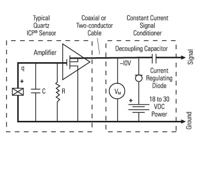
Figure 7: Typical Sensing System
The signal conditioner consists of a well-regulated 18 to 30 VDC source (battery or line-powered), a current-regulating diode (or equivalent constant current circuit), and a capacitor for decoupling (removing the bias voltage) the signal. The voltmeter (VM) monitors the sensor bias voltage (normally 8 to 14 VDC) and is useful for checking sensor operation and detecting open or shorted cables and connections.
The current-regulating diode is used instead of a resistor for several reasons. The very high dynamic resistance of the diode yields a source follower gain which is extremely close to unity and independent of input voltage. Also, the diode can be changed to supply higher currents for driving long cable lengths. Constant current diodes, as shown in Figure 8, are used in all of PCB's battery powered signal conditioners. (The correct orientation of the diode within the circuit is critical for proper operation.) Except for special models, standard ICP® sensors require a minimum of 2 mA for proper operation.
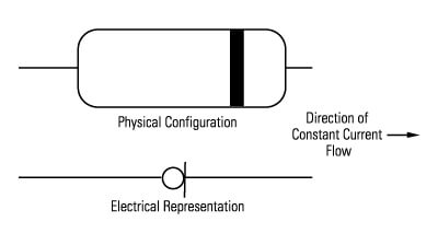
Figure 8: Constant Current Diode
Present technology limits this diode type to 4 mA maximum rating; however, several diodes can be placed in parallel for higher current levels. All PCB line-powered signal conditioners use higher capacity (up to 20 mA) constant current circuits in place of the diodes, but the principle of operation is identical.
Decoupling of the data signal occurs at the output stage of the signal conditioner. The 10 to 30 µF capacitor shifts the signal level to essentially eliminate the sensor bias voltage. The result is a drift-free AC mode of operation. Optional DC coupled models eliminate the bias voltage by use of a DC voltage level shifter.
Effect of Excitation Voltage on the Dynamic Range of ICP® Sensors
The specified excitation voltage for all standard ICP® sensors and amplifiers is generally within the range of 18 to 30 volts. The effect of this range is shown in Figure 9.
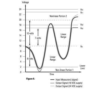
Figure 9: Typical Voltage Mode Systems
To explain the chart, the following values will be assumed: VB = Sensor Bias Voltage = 10 VDC
VS1 = Supply Voltage 1 = 24 VDC
VE1 = Excitation Voltage 1 = VS1 -1 = 23 VDC
VS2 = Supply Voltage 2 = 18 VDC
VE2 = Excitation Voltage 2 = VS2 -1 = 17 VDC
Maximum Sensor Amplifier Range = ±10 volts Note that an approximate 1-Volt drop across the current limiting diode (or equivalent circuit) must be maintained for correct current regulation. This is important, as two 12 VDC batteries in series will have a supply voltage of 24 VDC, but will only have a 23 VDC usable sensor excitation level.
The solid curve represents the input to the internal electronics of a typical ICP® sensor, while shaded curves represent the output signals for two different supply voltages.
In the negative direction, the voltage swing is typically limited by a 2 VDC lower limit. Below this level, the output becomes nonlinear (nonlinear portion 1 on graph). The output range in the negative direction can be calculated by:
Negative Range = VB-2 (Equation 4)
This shows that the negative voltage swing is affected only by the sensor bias voltage. For this case the negative voltage range is 8 volts.
In the positive direction, the voltage swing is limited by the excitation voltage. The output range in the positive direction can be calculated by:
Positive Range = (Vs - 1) - VB = VE - VB (Equation 5)
For a supply voltage of 18 VDC, this results in a dynamic output range in the positive direction of 7 volts. Input voltages beyond this point simply result in a clipped waveform as shown.
For the supply voltage of 24 VDC, the theoretical output range in the positive direction is 13 volts. However, the microelectronics in ICP® sensors are seldom capable of providing accurate results at this level. (The assumed maximum voltage swing for this example is 10 volts.) Most are specified to ±3, ±5 or ±10 volts. Above the specified level, the amplifier is nonlinear (nonlinear portion 2 on graph). For this example, the 24 VDC supply voltage extended the usable sensor output range to +10/-8 volts.