IMI Sensors technical support is unmatched. Years of application engineering experience have yielded technical tips to help maintenance teams to protect their critical machinery against unscheduled downtime. Check them out!
Patented “Linear Adjust Design” Mechanical Vibration Switch
Industry-Leading Design Providing Tremendous Performance Improvements
IMI Sensors offers several switch products at various levels of functionality and price. The most economical of the switch products is the patented “linear adjust” mechanical switch (Model 685AX9). It is ideal for a variety of industrial applications, including cooling tower condition monitoring and HVAC equipment predictive maintenance.
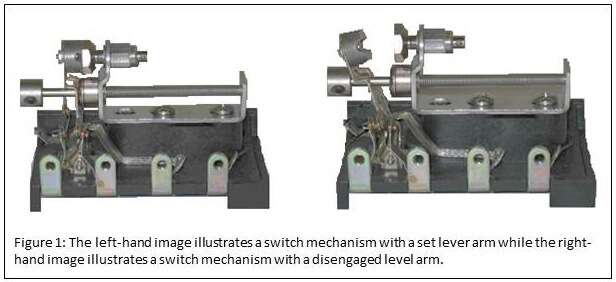
The basic design of a mechanical switch involves a small, rare earth magnet mounted on one end of a spring-loaded lever arm and a mass mounted on the other end. The base of the arm is mechanically connected to the throw of an electrical relay. To hold the lever arm in a set position, the magnetic attraction between the magnet and a piece of magnetic material (usually steel) must be stronger than the combined force of the spring plus inertial forces on the mass. The amount of magnetic attraction is dependent upon the position of the magnet in respect to the magnetic material. That position can be modified by manipulating an adjustment screw. When the combined force of the spring plus inertial forces on the mass are greater than the attractive forces between the magnet and the magnetic material, the arm disengages from an armed position and subsequently causes the electrical relay to change state. The mass is sensitive to inertial forces on all three axes. See Figure 1 for an illustration of a set lever arm and a disengaged lever arm.
First-generation mechanical switches have the magnet and magnetic material in a parallel position to one another. See Figure 2. The parallel design has two major flaws:
- The relationship between change in magnetic force and change in adjustment knob is non-linear. This is a result of the fact that the adjustment knob changes the distance between the magnet and the magnetic material and that distance is in a non-linear relationship with magnetic force. See Figure 3.
- An inertial force on the X axis is far more influential on the mass than inertial forces in other directions. See Figure 4.
To remedy the two above-referenced flaws, IMI Sensors developed a new “linear adjust” design that places the magnet and magnetic material in a perpendicular position to one another. The design, which was awarded a patent by the US Patent and Trademark Office (US Patent No 9,024,712) in May 2015, is shown in Figure 5. The patented design offers two major performance enhancements over the parallel design:
- The relationship between change in magnetic force and change in the adjustment knob is linear. This is a result of the fact that changes to the adjustment knob only alter overlap between the magnet and magnetic material in the “linear adjust” design rather than altering the gap distance between the magnet and the magnetic material. Regardless of adjustment knob position, the gap distance between the magnet and magnetic material stays unchanged.
- Inertial forces in all directions have a much more similar effect on the position of the mass. The greater similarity in effect of the inertial forces is shown in Figure 6.
| |
Parallel |
Linear Adjust |
|
Force Required to Trip Switch (lbs)
|
+ X
|
50
|
60
|
|
- X
|
25
|
30
|
|
Y
|
160
|
75
|
|
Z
|
160
|
85
|
Figure 6: Inertial forces in all directions have a much more similar effect on the position of the mass in a "linear adjust" switch compared to the parallel design switch.